Skip to content
< All Topics

Logic Configurator

The Logic Configurator is accessible as a view within in Experior 7s user interface. It allows you to configure logical relations between the elements of the scene in a graphical editor. You can use the Logic Configurator to create flow simulations by adding logical operations and connecting them with elements of the scene. The Logic Configurator provides element inputs and outputs and allows you to configure the relations between them without a controller.

See the video below for a quick demonstration:

Creating Connections

To establish a relation between blocks, follow these steps:

  1. Click an output of one assembly block.
  2. Hold down the left mouse button and draw a connecting line to the input of another assembly block.

The connection between two blocks is indicated by a solid line. Connections can only be established between inputs and outputs of the same type.

To remove a connection, follow these steps:

  1. Right-click the connection in the Logic Configurator.
  2. Click Delete from the contextual menu.

NOTE: Each input can be connected to only one signal, whereas each output signal can have multiple connections.

Good Practices

Accessing the Commands

You can access the contextual menu commands by typing the first letter of the command.

Examples:
Right-click in the Logic Configurator view to open the contextual menu and type:

  • t to create a Timer block.
  • c + c to create a Counter block because this is the second command in the list starting with c.
  • m + n to create a Number block. It serves as a shortcut to use the command Mathematics > Number.

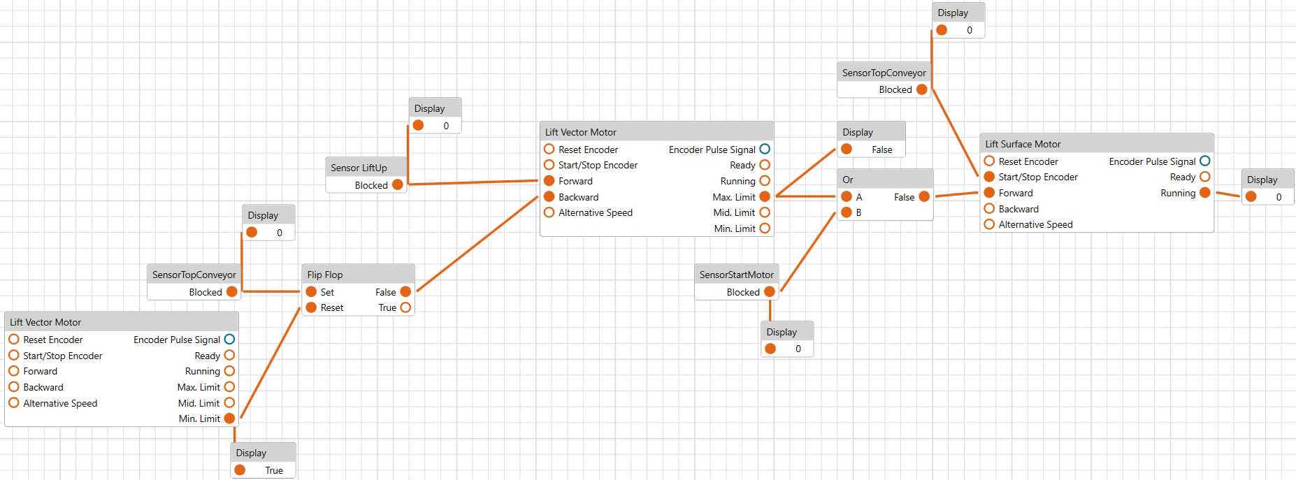
Creating Multiple Blocks for the Same Assembly

To create a clear arrangement of blocks and connecting lines for the same assembly or motor, you can use multiple blocks. To achieve this:

  1. Select the assembly or motor in the scene.
  2. Right-click anywhere in the Logic Configurator view and click Create Register Node(s) several times until the desired number of blocks is created.
NOTE: If you create multiple instances of the same assembly or motor and you establish multiple connections to the same input, the block uses the last updated input value as the default input.

Example:

To establish clear visibility of connecting lines when representing an output signal located on the right-hand side of the assembly block (Basic Surface Motor 1 in this example) connecting to another block located on the left-hand side (Timer in this example), it is a good practice to create an additional instance of the block (Basic Surface Motor 1 in this example) and position it on the left-hand side (of the Timer block in this example).

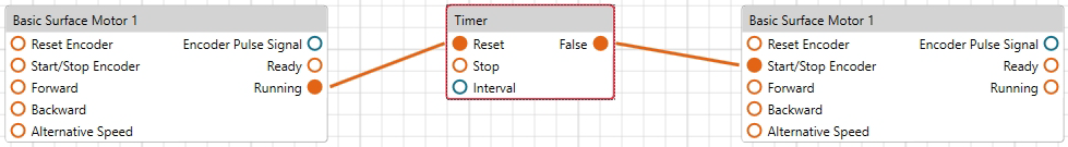
Displaying Boolean and Numerical Values

The values of Boolean and numerical inputs and outputs are, by default, not displayed for all blocks in the Logic Configurator. To make these values visible, create the following blocks and connect them to the inputs or outputs:

  • Boolean Display blocks to visualize Boolean outputs.
  • Number Display blocks to visualize numerical outputs.

Managing Blocks

To create blocks, right-click in the Logic Configurator and select a command from the contextual menu to create a specific block.

To remove a block, right-click the block and use the Delete command from the contextual menu or select the block and press the Delete key on your keyboard.

Configuring Blocks

You can configure a block in two different ways:

  • Select the block in the Logic Configurator and configure the corresponding parameters in the Properties view on the right-hand side of the EcoStruxure Machine Expert Twin window.
  • Create other blocks, for example, Mathematics blocks, and establish relations between the blocks within the Logic Configurator.