< All Topics
Adding an OPC Server and Symbols
Posted
Updated
ByKasper Vestrup
As an alternative to using Fetch/Write, an OPC Server can also be used to test a model. This guide shows how to use an OPC Server to program and run the basic psychics model example.
KEPServerEX from Kepware and its predefined variables will be used for this example.
The server should be running on the PC before this exercise is attempted.
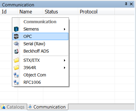
- First, click on the Communications tab on the right of the Experior window, just below where the Catalogs are displayed
- Now right click on the first line and select OPC
- Select the newly created OPC Server and in the Properties panel edit it like so
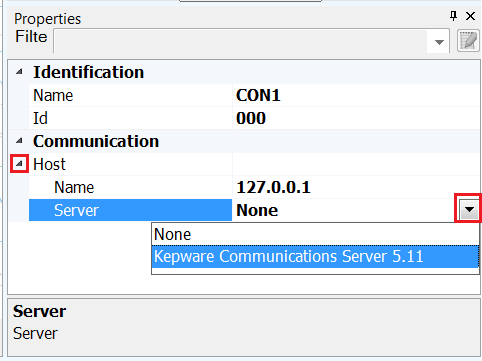
- If something other than Kepware is being used than that will appear in the dropdown instead
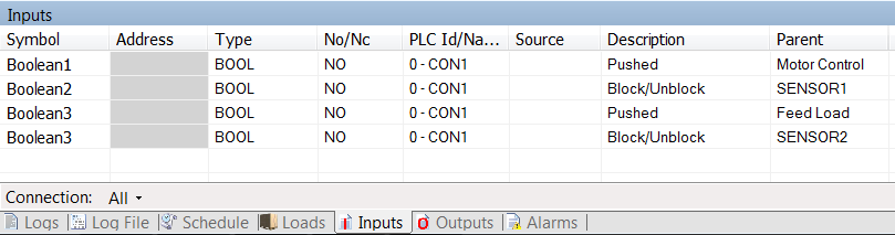
- The symbols and associated items are listed in the table below
INPUTS
Boolean1 Motor Control “Switch”
Boolean2 Feed Load “Button” & Feed Load “Sensor” (2nd Sensor in system)
Boolean3 Load In System “Sensor” (1st Sensor in system)
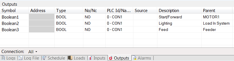
OUTPUTS
Boolean1 Motor Drive Control
Boolean2 Feeder “Feed Load” Control
Boolean3 Load In System “Lamp”- Select the switch called Motor Control in the Control Panel
- In the Properties panel, below PLC Input expand the section by clicking the arrow to the left of where it says On/Off
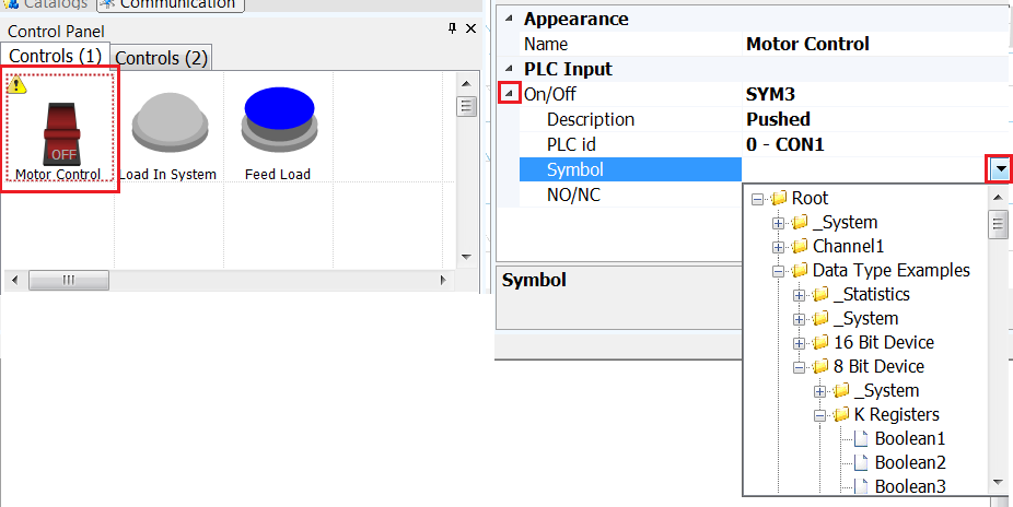
- In the Symbol field click the drop down button
- The structure of the OPC Server then appears as a drop down enabling the user to scroll through and select the correct symbols
- For this example the Booleans under K Registers is used
- Expand the folder that contains the symbols
- Select the symbol Boolean1 to have it added to the properties of the item
- Now select the push button Feed Load
- In the Properties scroll down to PLC Input and expand the section by clicking the arrow to the left of where it says Pushed
- Expand the folder that contains the symbols
- Select the symbol Boolean2 to have it added to the properties of the item
- Now select the second sensor that was added to the model
- In the Properties scroll down to PLC Input and expand the section by clicking the arrow to the left of where it says Blocked
- Expand the folder that contains the symbols
- Select the symbol Boolean2 to have it added to the properties of the item
- Now select the first sensor that was added to the model
- In the Properties scroll down to PLC Input and expand the section by clicking the arrow to the left of where it says Blocked
- Expand the folder that contains the symbols
- Select the symbol Boolean3 to have it added to the properties of the item
- Select the Motor by clicking any of the red arrows in the model
- In the Properties scroll down to where it says Operations and expand the section for Forward (Output) by clicking on the arrow to the left of it
- Expand the folder that contains the symbols
- Select the symbol Boolean1 to have it added to the properties of the item
- Now select the Feeder, that is the triangle/arrow located on the first straight that was added to the model
- Scroll down the Properties to the section PLC Output and expand the section for Feed by clicking on the arrow to the left of it
- Expand the folder that contains the symbols
- Select the symbol Boolean2 to have it added to the properties of the item
- Lastly select the Lamp in the Control Panel
- In the Properties scroll down to PLC Output and expand the section under Lighting by clicking the arrow to the left of it
- Expand the folder that contains the symbols
- Select the symbol Boolean3 to have it added to the properties of the item
- When finished the Inputs and Outputs tabs should look like so