Assembly Configuration
Overview
When you build an assembly the Assembly Configuration object can automatically handle:
- Rendering of parts, measures and other assemblies (sub-assemblies)
- Disposing of parts and sub-assemblies
- Picking
- User movement and rotation with the mouse
- Locking and unlocking
- Selecting and deselecting
If you want to manually handle some of these methods you must override the according method (or property) in the Assembly class:
- public virtual void Move(Vector3 delta)
- public virtual float Yaw
- public virtual Vector3 Position
- public virtual void Lock()
- public virtual void UnLock()
- public virtual PickResult Pick(Vector3 rayStart, Vector3 rayDirection)
- public virtual void Render()
- public virtual void Select()
- public virtual void DeSelect()
- public virtual void Dispose()
This part of the wiki will explain how to:
- Add a part, a measure or another assembly to the assembly
- Position, rotate and move parts using local coordinates
- Use movement and angular movements of parts
- Use the coordinate systems
All examples in this document refer to the assemblies in the DeveloperSamples catalog.
Naming the coordinates
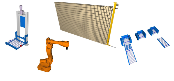
When referring to an assembly’s local coordinates the coordinate system on the blue conveyor in Figure 1 is being referred to. These coordinates will always follow the assembly.
The Global coordinates always refer to the coordinate system of the 3D environment with axis names: X, Y, Z, also illustrated in Figure 1. This coordinate system is never moved.
The third coordinate system, placed in the blue cube in Figure 1, is the parts own coordinate system. This coordinate system is not as important as the two others and is mainly used when using a LocalRotationPoint.
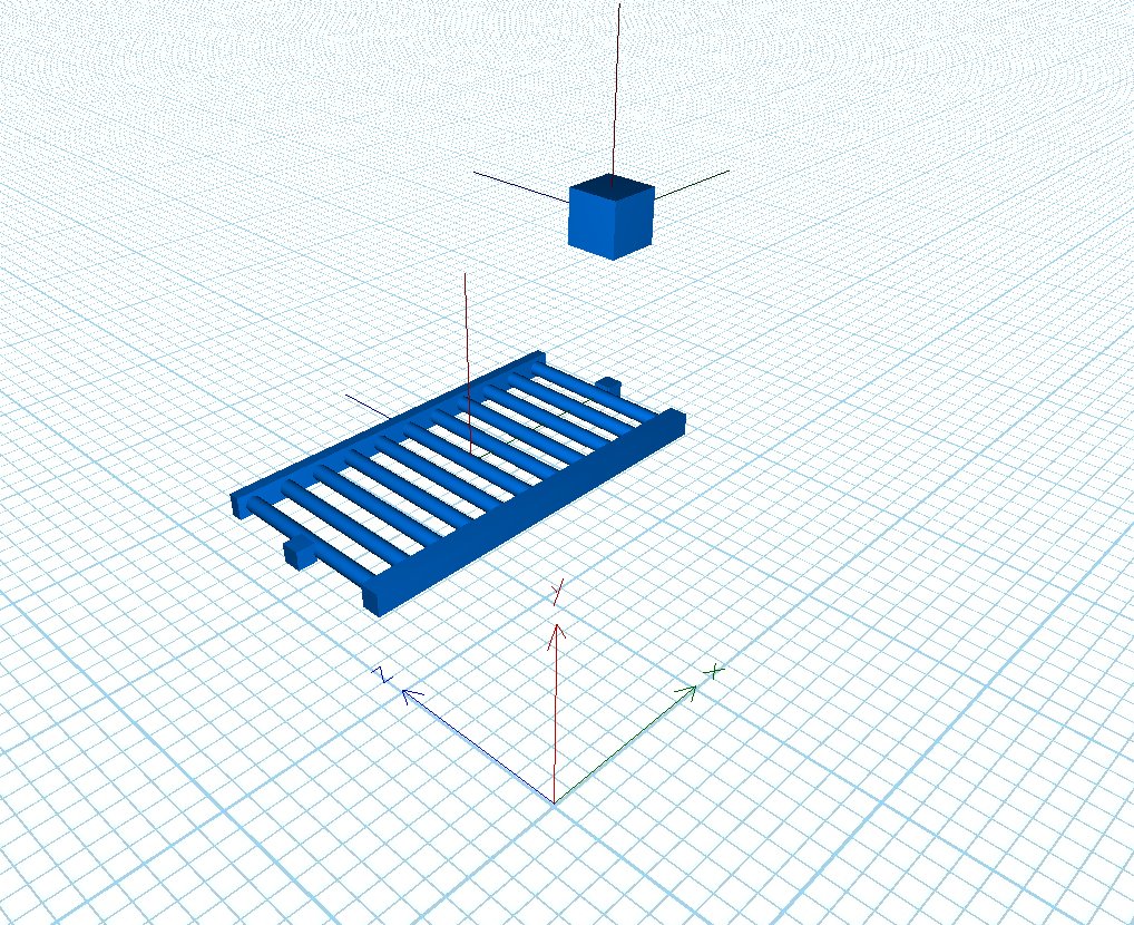
Figure 1
Classes, methods and properties
The Assembly Configuration object is not accessed directly. But it is used indirectly when using the following methods and properties in the RigidPart, Assembly and Measure classes.
For the RigidPart class the involved methods and properties are:
- public Vector3 LocalPosition
- public float LocalYaw
- public float LocalPitch
- public float LocalRoll
- public Vector3 LocalRotationPoint
- public void LocalMovement(Vector3 localVelocity, float lengthToMove)
- public void LocalMovement(Vector3 localVelocity, float lengthToMove, float rampUpLength, float rampDownLength)
- public void LocalAngularMovement(Vector3 angularVelocity, Vector3 radiansToRotate)
- public event FinishedMoving LocalMovingFinished;
- public event FinishedRotating LocalRotationFinished;
- public CoordinateSystem LocalCoordinateSystem
For the Assembly class the involved methods are:
- protected RigidPart Add(RigidPart part)
- protected RigidPart Add(RigidPart part, Vector3 localPosition)
- protected RigidPart Add(string name, RigidPart part)
- protected RigidPart Add(string name, RigidPart part, Vector3 localPosition)
- protected Assembly Add(Assembly assembly, Vector3 localPosition)
- protected Assembly Add(Assembly assembly, Vector3 localPosition, bool visible)
- protected Core.Dialog.Measure Add(Core.Dialog.Measure Measure)
- protected CoordinateSystem Add(CoordinateSystem c)
- protected bool Remove(RigidPart part)
- protected bool Remove(Core.Dialog.Measure measure)
- protected bool Remove(Assembly assembly)
- public Vector3 LocalPosition
- public float LocalYaw
- public float LocalPitch
- public float LocalRoll
For the Measure class the involved methods are:
- public Vector3 LocalStartPosition
- public Vector3 LocalEndPosition
Note that all methods and properties begins with Add, Remove or Local.
Add parts, measures and assemblies
Adding parts
Adding a part to an assembly is done by the method Add(RigidPart part).
Example: (See Sample0.cs for full source code)
Add(new Cube(Color.Wheat, 0.5f, 0.5f, 0.5f));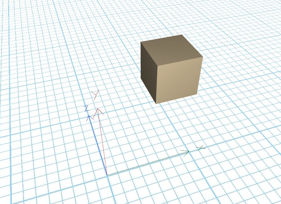
Figure 2
Without further code the cube can now be selected, deselected, locked, unlocked, picked, moved and rotated.
To remove the part from the assembly:
protected bool Remove(RigidPart part)
Note: this does not dispose the part.
Positioning of parts using LocalPosition
In Sample1.cs it is shown how to add 100 cubes and position them using the LocalPosition property.
Example: (See Sample1.cs for full source code)
for (int i = 0; i < 10; i++)
{
    for (int j = 0; j < 10; j++)
    {
        Add(new Cube(Color.Wheat, 0.5f, 0.5f, 0.5f), new Vector3(0, i, j));
    }
}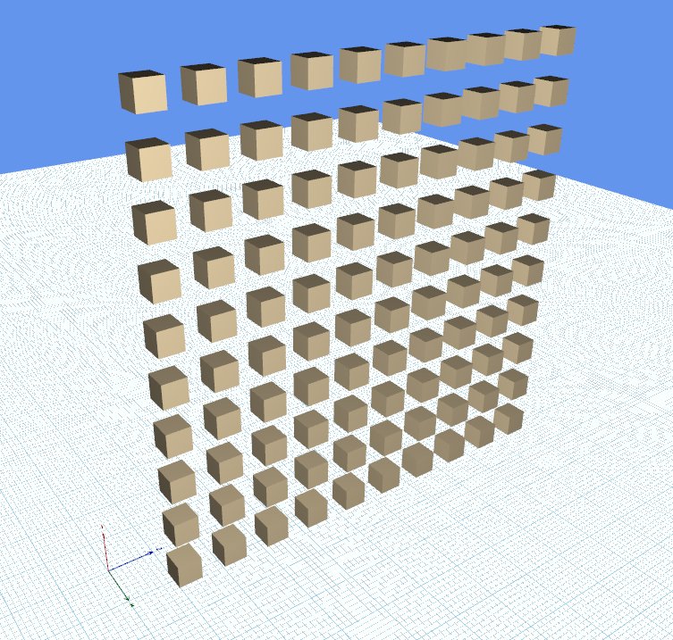
Figure 3
When a part is added to an assembly it is recommended that the part is positioned using the LocalPosition property.
The property called Position always refers to a part’s global position.
Rotating parts using LocalYaw, LocalPitch and LocalRoll
In Sample2.cs two cubes are added. The LocalPitch value of the blue cube has been set to 0.56f.
Default values for LocalYaw, LocalPitch and LocalRoll are 0 and the units are radians.
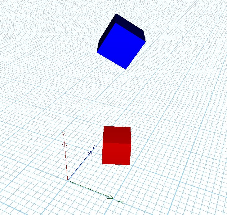
Figure 4
Note: If a part is not added to an assembly, the properties Yaw, Pitch and Roll will refer to the global orientation.
When a part is added to an assembly these values refer to the rotation in the parts own coordinate system. See also the section about LocalRotationPoint.
Adding another assembly and a measure
It can be useful to add another assembly and treat it as a part (or as a sub-assembly). This can be done with the method:
- protected Assembly Add(Assembly assembly, Vector3 localPosition)
When the assembly has been added it can be positioned and rotated with the following methods:
- public Vector3 LocalPosition
- public float LocalYaw
- public float LocalPitch
- public float LocalRoll
LocalPosition, LocalYaw, LocalPitch and LocalRoll all use the coordinate values of the assembly that the sub-assembly has been added to.
To add a measure use the following method:
- protected Core.Dialog.Measure Add(Core.Dialog.Measure Measure)
When constructing the measure a start position and an end position must be provided. Local coordinates must be used for these values as they are used when adding the measure to the assembly as the LocalStartPosition and LocalEndPosition.
If later on these values need changing use the following measure methods:
- public Vector3 LocalStartPosition
- public Vector3 LocalEndPosition
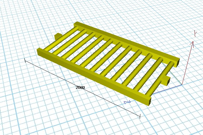
Figure 5
The file Sample3.cs contains an example on how to add an existing conveyor and a measure as illustrated in Figure 5.
To remove the assembly or the measures use the following methods:
- protected bool Remove(Assembly assembly)
- protected bool Remove(Core.Dialog.Measure measure)
Note: this does not dispose of the assembly.
Linear and angular movement (Physics mode)
LocalMovement and LocalAngularMovement
To create a movement of a part it is always possible to override the void Step(float deltatime) method in the Assembly and use this time-step to move the parts.
The Assembly Configuration gives you two methods to create movements without overriding the Step method.
One for a straight movement:
- public void LocalMovement(Vector3 localVelocity, float lengthToMove)
One for an angular movement:
- public void LocalAngularMovement(Vector3 angularVelocity, Vector3 radiansToRotate)
These methods are available for the RigidPart class as well as the CoordinateSystem class (see later section) but not for the Assembly class.
The parameter Vector3 angularVelocity has the form:
(Local yaw Velocity, Local pitch velocity, Local roll velocity)
It uses the units radians/second.
The parameter Vector3 radiansToRotate has the form:
(Delta yaw, Delta pitch, Delta roll)
It uses radians as units.
Note: if using a positive Local yaw Velocity a positive Delta yaw must be used as a stop condition, because the rotation is around the local Y-axis in positive direction. Likewise, if using a negative Local yaw Velocity a negative Delta yaw must be used.
To know when the movement has finished the following events can be subscribed to:
- public event FinishedMoving LocalMovingFinished;
- public event FinishedRotating LocalRotationFinished;
Example: (See Sample4.cs for full source code)
The method:
- LocalMovement(new Vector3(1, 0, 0), 1);
This will create a movement with velocity (1,0,0) in local coordinates which stops after 1 meter.
Note that the length must always be positive, otherwise the movement is ignored.
The method:
- LocalAngularMovement(new Vector3(1, 0, 0), new Vector3((float)Math.PI, 0, 0));
This will create a rotation which rotates around the local Y-axis with velocity 1 radian/second which stops when it has rotated PI degrees.
The method:
- LocalAngularMovement(new Vector3(-1, 0, 0), new Vector3(-(float)Math.PI, 0, 0));
This will create a rotation which rotates around the local Y-axis with velocity -1 radian/second which stops when it has rotated -PI degrees.
How to use coordinate systems
When more advanced movements are created it can be useful to have several coordinate systems. This is, for example, the case when constructing a robot as the one in the Robot class in the DeveloperSamples catalog. When using more than one coordinate system a hierarchy of coordinate systems can be used, meaning that a coordinate system can have a subsystem and a parent system. The top most coordinate system (the one having no parent system) is used as the local coordinate system of the assembly.
Robot class
In the Robot class in the DeveloperSamples catalog we use 5 coordinate systems as illustrated in Figure 8. The coordinate systems have been placed where the robot is able to move or rotate.
If the coordinate systems have been constructed and added to the assembly using the following method:
- protected CoordinateSystem AddCoordinateSystem(CoordinateSystem c)
Then parts can be added to the coordinate system. This can be done with either:
- coordinate0.AddPart(link0, new Vector3(-0.17f, 0.15f, 0));
or:
- link0.LocalCoordinateSystem = coordinate0;
- link0.LocalPosition = new Vector3(-0.17f, 0.15f, 0);
When a part has been added to a coordinate system the LocalPosition property of the part will refer to that coordinate system.
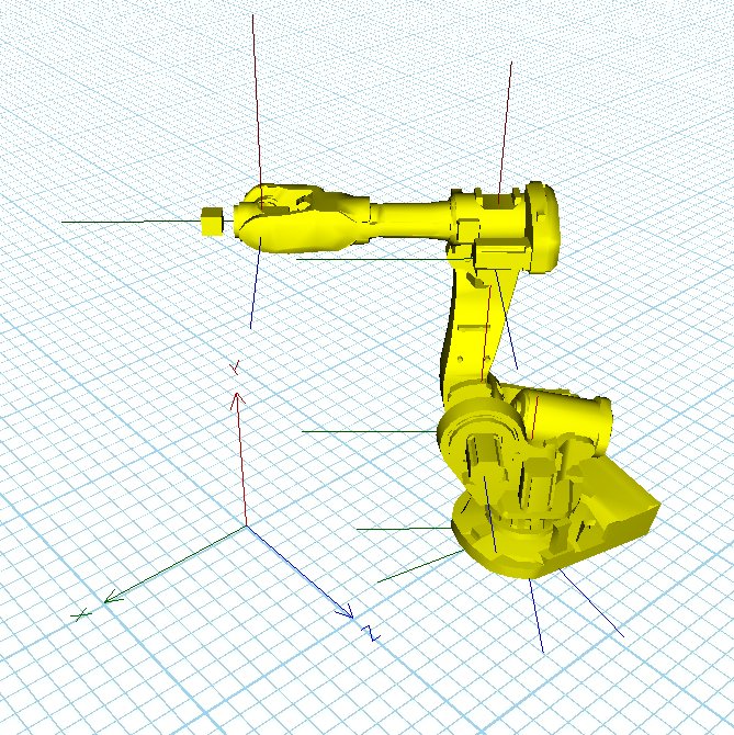
Figure 8
The coordinate system axes have the same colors as the coordinate system axes of the 3D environment of Experior, the X-axis is green, Y-axis is red and Z-axis is blue.
Constructing the Coordinate System
The coordinate system class has the following constructor:
- public CoordinateSystem(CoordinateSystem SubSystem, Vector3 SubSystemPosition)
Here it can be specified which coordinate system should be the subsystem and where it should be placed SubSystemPosition. The subsystem will automatically be assigned to the coordinate system which will function as its parent system.
If the coordinate system should not have any subsystem use the constructor:
- CoordinateSystem(null, Vector3.Empty);
Linear and Angular Movement of Coordinate Systems
The CoordinateSystem class has some of the same methods and events as the IRigidPart class:
- public void LocalMovement(Vector3 localVelocity, float lengthToMove)
- public void LocalMovement(Vector3 localVelocity, float lengthToMove, float RampUpLength, float RampDownLength)
- public void LocalAngularMovement(Vector3 angularVelocity, Vector3 radiansToRotate)
- public event FinishedMoving LocalMovingFinished
- public event FinishedRotating LocalRotationFinished
When these methods are used the coordinate system will rotate or move any parts that are added to the coordinate system.
Rotating a coordinate system relative its parent system
To rotate a coordinate system use the following method:
- public void RotateRelativeParent(float deltaYaw, float deltaPitch, float deltaRoll)
This will also rotate its subsystem if there is any.