Building a model in physics mode
This guide will cover constructing a model, adding controls and controllers, setting up PLC Inputs and Outputs on the components that need them and finally running and testing the model.
In this article a simple model using standard Experior components will be built and the guide will provide more information on some of the properties used by those components.
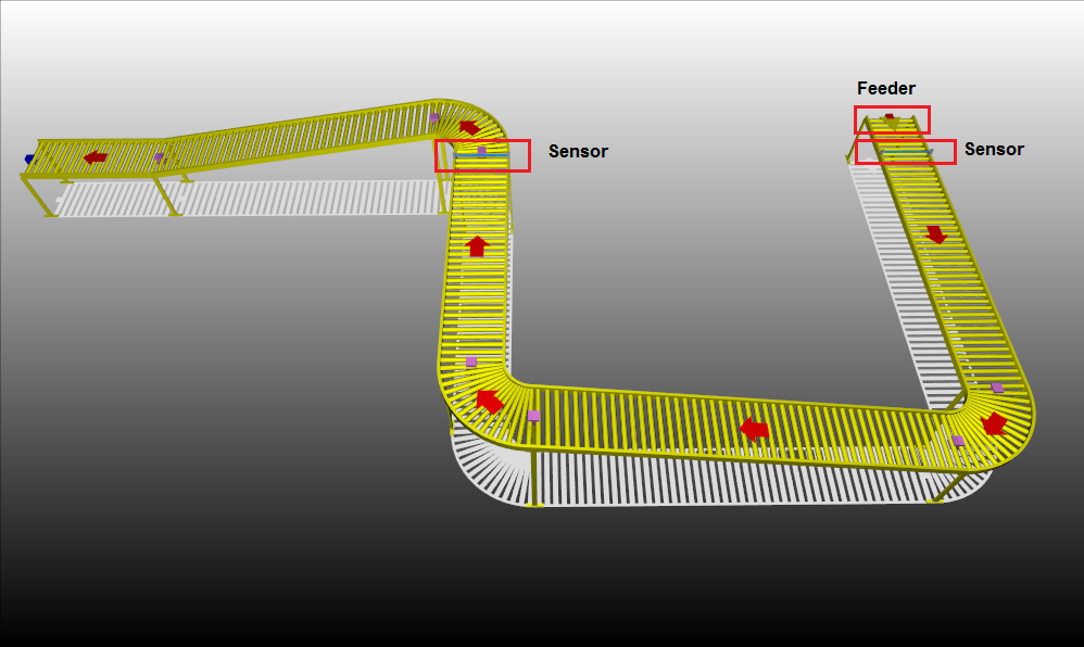
This is a screen-shot of what the model looks like when finished. Note the tracks are gold because they are locked in place.
Building the Model
- To begin select the Basic catalog by clicking the tab
- Then click and drag a Conveyor (Straight) into the construction area
- Adjust the length of the straight by either clicking and dragging from one of the endpoints or by selecting the straight and in the properties window scrolling down to Position and changing the first number in either the Start or End row to adjust the length
- As a note, tracks, by default, run from the red point to the blue point, so when attaching additional items opposite coloured points must be snapped together to ensure the model flows correctly
- Next a motor should be added to the straight
- To do this select the straight and right click it
- Then move down so Insert Motor is highlighted and then move across to Surface so that is now highlighted and finally click New
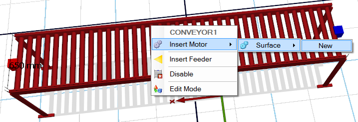
- Note the arrow that appears, this is the motor and indicates the direction in which it will be driving the conveyor
- A feeder now needs to be added to the conveyor, so once again right click on the conveyor, move down and click Insert Feeder

- Lastly a sensor needs to be added
- To do this click on the Sensor tab in the catalog area and then click and drag a Photoeye into the working area
- When dropped reselect the photoeye and drag it to the edge of the conveyor so that it also becomes highlighted as shown
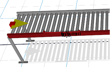
- Now press the CTRL button and the photoeye will automatically align and re-size itself so that it fits across the width of the conveyor
- Now a curved section of conveyor will be added to the blue end of the straight
- In the Basic catalog find the Curve(Clockwise) item and drag it across into the working area
- Drop it away from the straight so it can be worked on first
- Select the curve so that it is highlighted
- In the Properties panel scroll down and find Yaw under the heading Orientation
- Change this value from 0 to 180
- Now select and drag the curve to the blue end of the straight so the the blue and red points overlap and turn a pinkish colour
- Hold down CTRL when and it will snap the curve into place
- Lastly a motor needs to be added to the curve
- To do this select the curve and right click it
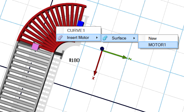
- Then move down so Insert Motor is highlighted and then move across to Surface so that is now highlighted and finally click MOTOR1
- This then adds a motor to the curve which shares the properties of the motor that was added to the straight
- Next a straight with a slight incline needs to be added
- As before select and drag a straight onto the working area
- Before connecting it to the curve, select it and in the Properties window scroll down to Position
- Adjust the second value in the End row to 1470, this changes the height at the end of the straight
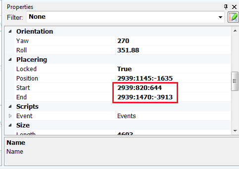
- Now the straight with an incline can be attached to the curve
- Now add a motor to the straight
- Add MOTOR1 in the same way as detailed for the curve above
- The next 4 parts to be added to the assembly are 2 curves, 1 straight and a photoeye sensor to go on the straight
- They will need to have their height adjusted to match the end of the straight that was just added
- The height of the parts will be 1470 and the value that needs modifying is the second one in the Position row
- These 3 parts will also have motors, to be added as MOTOR1 as before
- Finally two more straights need to be added, one with a downward slope and one short straight
- For the sloping straight the height should first be made 1470 in the second value of the Position row, then modify the second value in the End row to be 820
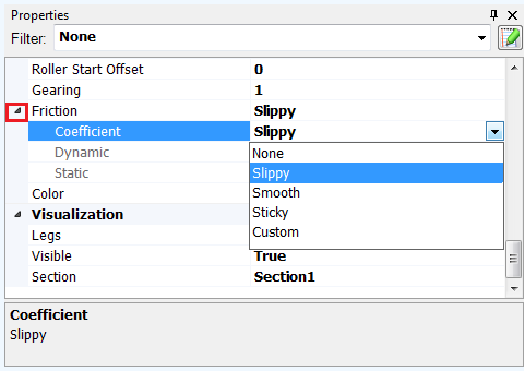
- Next scroll down the Properties to Friction
- Expand the section by clicking the arrow on the left
- Next using the Coefficient drop down change the value to Slippy
- This straight will not have a motor as a gravity lane is being simulated here
- Insert the last straight and ensure the height is set at 820 and link it to the downward sloping straight
- Add MOTOR1 to the last straight
Adding Controls
Now some basic controls need to be added to the model.
The Control Panel is located directly below the Catalog/Communications pane.
- Firstly a 2 state switch to control the motor should be created
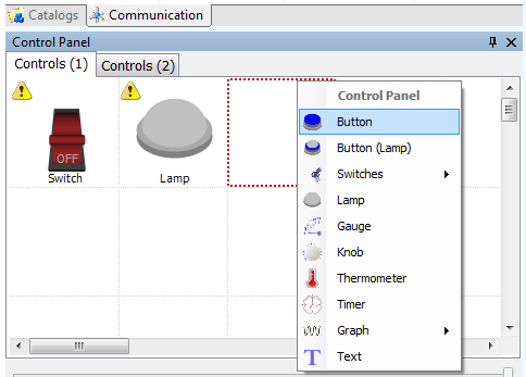
- Select the first empty square in the Control Panel, move down to Switches
- On the pop out move across to 2 States and then on the final pop out select Classic
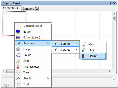
- Now add a lamp, this will be used to show when a load has entered the simulation
- On the second empty square in the Control Panel select it, right click and select Lamp on the drop down
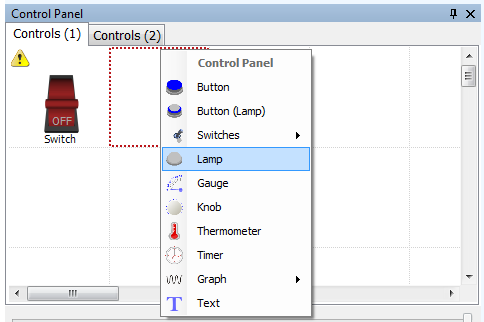
- Lastly a simple push button will be added. This will be one method of introducing loads into the simulation
- On the third square select it, right click and then scroll down and select Button to insert a push button
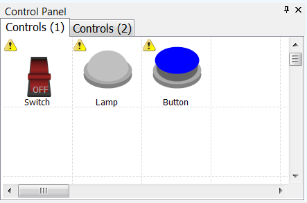
- So now the Control Panel should look like this
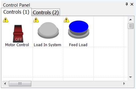
- To rename the controls to make them more easily identifiable, select them and in the Properties pane under Appearance change the Name field
Adding Communications and Symbols
Some of the items in the model have yellow triangles with exclamation marks in them next to them.
The reason for this is because the items or controls are waiting to be linked to a PLC and have either an Input or an Output associated to them.
For the purpose of this exercise three methods for testing inputs and outputs within Experior will be covered. These can be used as a temporary stopgap if you don’t have a PLC, SoftPLC or Controller available for testing. Click on the desired method, follow the guide and return to this guide when ready to run the simulation:
Siemens Fetch & Write
Adding an OPC Server and Symbols
TwinCAT 3 SoftPLC
Running the Simulation
- To run the simulation the communication device(s) must be connected and running
- If using the Fetch/Write method then in the Communications pane double click on the Write device and then double click on the Fetch device
- If an OPC Server is being used then it should automatically connect when the model is loaded, otherwise double click the OPC line in the Communications pane
- If the Beckhoff TwinCAT SoftPLC is being used then double click on the entry to connect to the system after the SoftPLC has been set to run
- The Communications pane should now look like this:

- Now press the Play button located at the top of the screen to start the simulation
- Click the Motor Control switch into the ON position, so the arrows representing the motors change colour from red to green signifying that the motor is now running
- Press the Feed Load button to enter a load into the system and watch it as it passes through the system
- Note how the lamp lights as the load passes through the first sensor
- Also note how when the load passes through the second sensor a new load is introduced into the system
